
")

Readers are invited to the description of the scheme and the alleged explanation of the device that allows to feed from incandescent autotransformer incorporated into a self-sustaining oscillating regime of special self-oscillating circuit. The prototype served as a publication in the conference proceedings "Aluminum of Ural". Heated interest in the students who attended classes Mug "Ether" in 1999-2000 in the Ural State Technical University.
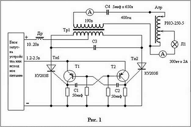
Fig. 1
The original version was designed for easy arc ignition low voltage and keeping it burning in the absence of any special plasters metal electrodes. Doug is really easy to light up when the electrodes included in the gap between the inductor Др. and transformer Тр. (see. Fig. 1).
As a power source or running used alkaline battery, which is connected in parallel to the rectifier. Two battery fueled multivibrator transistors T1 and T2. As the capacitors C1 and C2 used electrolytic 50-100 microfarads. The quality C3 - battery electrolytic capacitors included anti-series. Best results are obtained when the capacitor bank is divided into two portions, a midpoint connects to a midpoint of the transformer Тр1. Thyristors Tи, Tи2 КУ203Б type were used, as they allow to have a little time off (about 10 microseconds) and, in addition, they can be connected in parallel to the three pieces that can provide operating current up to 50 Amps. They are allowed to get in the winding Tр1 sawtooth current varies linearly and the voltage of a rectangular shape. This is the most important thing! Then, when a voltage is applied across the capacitor C4, having a capacity of 5 microfarads (650 volts) Autotransformer "Aтр" type PH0-250-5 included in a self-oscillating mode is self-sustaining, which is achieved by moving both of its engines associated with sliding roller contacts. Current. initially consumed by "Aтр", together with its attached lamp L1 300 watts higher than 2A, but after the excitement of the autotransformer, the current can be reduced by raising up to failure, top scheme Aтр engine; reduced to 0,1-0,2 Ampere. That, the lamp is lit and that the current consumed by Tp1, significantly reduced, directly points to the generation, though not very big, but a substantial electric power ferromagnetic core material. The frequency of the linear power saws up to 400 Hz. Limitation is due to the use of electrolytic capacitors.
We warn those who wish to repeat experiences that reduce the probability of failure of capacitors because of gas should be applied in the assembly of "C3" for voltage of 300-450 volts. It is not always "electrolytes" have the capacity, which is listed on their body. You should check Multimeter. Tested and cooling these capacitors (in the first experiments) water poured into the vessel. Cooling occurs, but it is a loss of energy. It is better to choose "electrolytes" the same capacity. The idea was that having a system of auto-transformers, generators, run it from the battery, and then send the energy increment as battery charging, and on any Energy. The increase in energy due not only to the rotation of the permanent magnetic moments, "packed" in the domains of metal, but also the rotation of the spins of the particles more quickly arising and disappearing near the iron nuclei. The candidate for this role can be a heavy unstable "electron", called a muon. It can quickly arise due to processes of weak interaction of pions, "adhering" to the iron cores of the physical vacuum in the presence of trace iron lattice "helium-4." Chaffee probably succeeded somehow clear from these iron impurities, and to receive a giant magnetic permeability of more than one million. Clearly, this iron, high purity, is no longer to give additional magnetic "echo" in the exciting winding. Therefore, as the ferromagnetic material can be applied to iron ore - magnetite having the formula Fe3O4.
G.I. Nikon, a senior lecturer in metallurgy branch of Ural State Technical University.